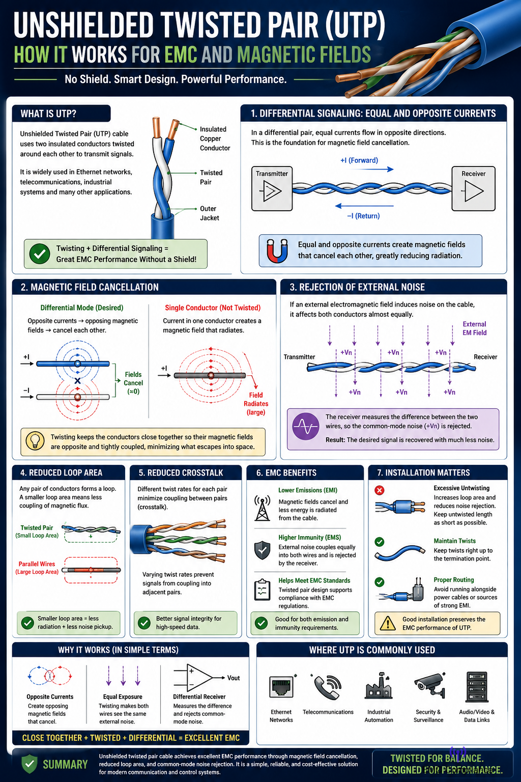
Twisted Pair
How Unshielded Twisted Pair Cable Works for EMC and Magnetic Field Reduction
Unshielded Twisted Pair (UTP) cable is one of the most widely used transmission media in modern electronics and communications. It is commonly found in Ethernet networks, telecommunications systems, industrial control equipment, and data communication links. Although UTP cable contains no metallic shield, it can provide surprisingly good immunity to electromagnetic interference (EMI) and excellent electromagnetic compatibility (EMC) performance when installed correctly. The secret lies in the twisting of the conductors.
A UTP cable consists of two insulated conductors twisted around each other at a regular rate. Signals are typically transmitted as differential signals, meaning that equal currents flow in opposite directions through the two conductors. One wire carries current toward the load while the other carries the return current. Because the currents are equal and opposite, the magnetic fields generated by the conductors largely cancel each other out.
This magnetic field cancellation is one of the key reasons twisted pair cables are so effective. Every conductor carrying current produces a magnetic field. If two conductors are separated by a significant distance, their magnetic fields can extend into the surrounding environment and potentially interfere with nearby equipment. By placing the conductors close together and twisting them, the opposing magnetic fields overlap and cancel, dramatically reducing the net field radiated from the cable.
The twisting itself provides an additional benefit. If the cable passes through an external electromagnetic field, each conductor experiences approximately the same amount of interference over the length of the cable. Because the wires continually exchange positions as they twist, neither conductor is consistently exposed to more interference than the other. This equal exposure causes unwanted noise to appear almost identically on both wires.
At the receiving end, differential receivers measure the voltage difference between the two conductors rather than the voltage of either conductor with respect to ground. Since the induced noise appears equally on both wires, it is largely rejected by the receiver. This characteristic is known as common-mode noise rejection and is one of the primary reasons twisted pair systems are highly resistant to electrical interference.
From an EMC perspective, twisted pair cables help address both emission and immunity requirements. EMC regulations generally require electronic systems to avoid generating excessive electromagnetic emissions while also remaining resistant to external interference. Because twisted pairs minimize magnetic field radiation and reduce susceptibility to incoming noise, they contribute significantly to meeting EMC compliance requirements.
The reduction of loop area is another important factor. Any pair of conductors carrying current forms a current loop. Larger loops act as more efficient antennas, both transmitting and receiving electromagnetic energy. Twisting the conductors together minimizes the average loop area along the cable length. A smaller loop area means less magnetic flux can couple into or out of the cable, reducing both radiated emissions and noise pickup.
In high-frequency applications, such as Ethernet communication, the twist rate becomes particularly important. Different pairs within a network cable are often twisted at different rates. This prevents the pairs from coupling energy into one another and reduces a phenomenon known as crosstalk. Crosstalk occurs when signals from one pair induce unwanted voltages in an adjacent pair. By varying the twist rates, the coupling between pairs is minimized, allowing multiple high-speed signals to coexist within the same cable.
Another advantage of UTP cable is that it achieves these EMC benefits without the cost, weight, and grounding requirements associated with shielded cables. Shields can be highly effective when properly grounded, but incorrect grounding may actually worsen EMC performance by creating ground loops or allowing shield currents to flow. Twisted pair technology avoids many of these issues while maintaining excellent signal integrity.
The effectiveness of twisted pair cable depends heavily on maintaining the twists throughout the installation. Excessively untwisting the conductors during termination increases loop area and reduces noise rejection capability. For this reason, network standards specify the maximum amount of untwisted conductor that can be exposed at connectors and termination points.
In industrial environments, where motors, variable-frequency drives, relays, and switching power supplies generate significant electromagnetic noise, twisted pair wiring is often the first line of defense against interference. Even without shielding, properly installed twisted pair cables can provide excellent performance by exploiting the natural cancellation of magnetic fields and the rejection of common-mode noise.
Unshielded twisted pair cable works by keeping two conductors close together and continuously twisting them along their length. The opposing currents generate magnetic fields that largely cancel each other, reducing radiated emissions. The twisting also ensures that external interference affects both conductors equally, allowing differential receivers to reject the noise. Through magnetic field cancellation, reduced loop area, and common-mode noise rejection, UTP cable provides an elegant and cost-effective solution for achieving good EMC performance in a wide range of electronic and communication systems.