Conducted emissions electromagnetic compatibility (EMC) measurement evaluates the unwanted electrical noise that an electronic device places onto its power lines. Unlike radiated emissions, which travel through the air, conducted emissions propagate along cables, most commonly the AC mains supply. These emissions are typically measured in the frequency range of 150 kHz to 30 MHz, where switching power supplies, digital clocks, and power electronics generate significant noise energy. Because power lines are shared infrastructure, excessive conducted noise from one product can interfere with other equipment connected to the same supply network.
Conducted emissions testing is required to ensure that electronic equipment does not disturb radio communications, safety systems, or other electronic products. Regulatory authorities around the world mandate EMC compliance before products can be legally sold. In the United States, compliance is governed by the Federal Communications Commission under FCC Part 15. In Europe, products must comply with the EMC Directive administered by the European Commission to carry CE marking. Internationally, limits and measurement methods are defined by standards developed by the International Electrotechnical Commission, particularly CISPR standards such as CISPR 32. Meeting these requirements ensures market access and reduces the risk of fines, product recalls, or shipment delays. Beyond regulatory necessity, good conducted emissions performance usually reflects sound engineering practices, such as proper grounding, optimized PCB layout, and controlled switching behavior.
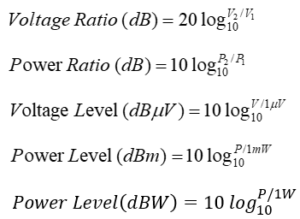
The conducted emissions test setup is standardized to ensure repeatability and consistency across laboratories. The core component of the setup is the Line Impedance Stabilization Network (LISN). The LISN provides a defined impedance (typically 50 Ω / 50 µH), isolates the equipment under test (EUT) from external power line noise, and couples the noise voltage from the EUT to the measurement receiver. The EUT is placed on a non-conductive table approximately 80 cm above a grounded reference plane and positioned at specified distances from vertical and horizontal ground planes. The AC supply feeds the LISN, which in turn powers the EUT. An EMI receiver or spectrum analyzer connected to the LISN measures the noise voltage in dBµV. Testing is normally performed inside a shielded room or semi-anechoic chamber to minimize external interference.
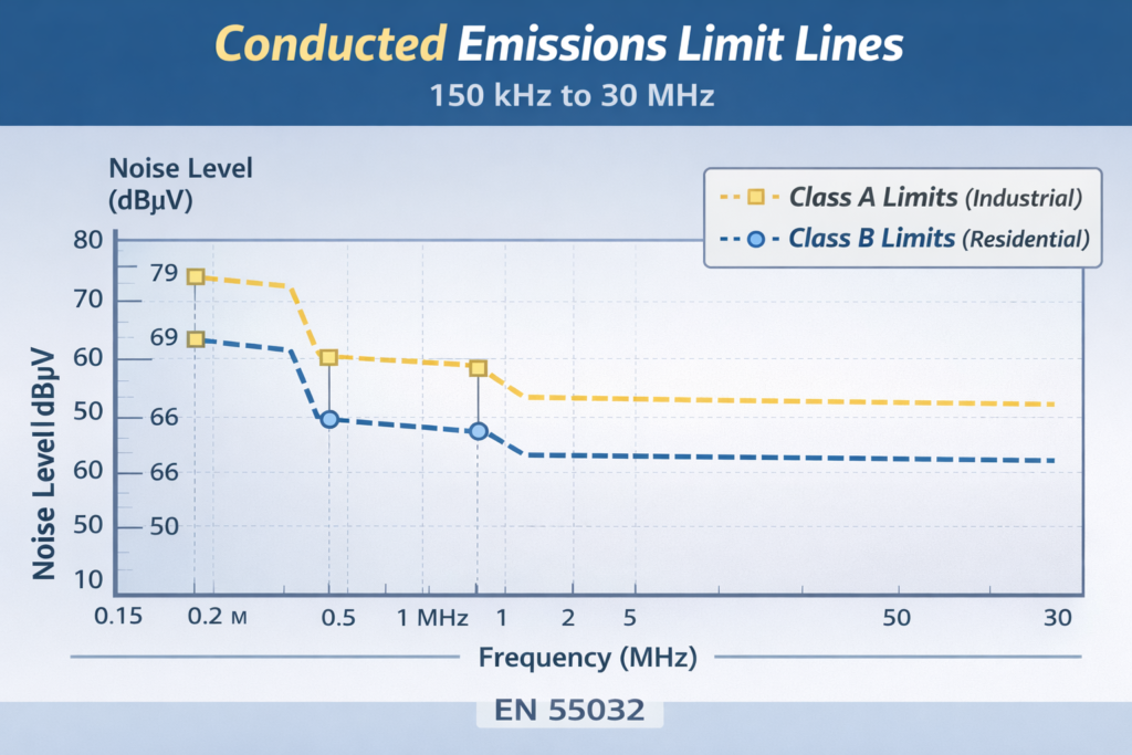
The measurement procedure begins by operating the EUT in a worst-case mode that produces maximum emissions, such as full load or maximum processing speed. A preliminary scan is typically performed using a peak detector across the required frequency range to identify dominant emission frequencies. Once critical frequencies are identified, final measurements are taken using quasi-peak and average detectors, as required by the applicable standard. The measured results are then compared against the limit lines specified for either Class A (industrial environments) or Class B (residential environments), with Class B limits being more stringent. To ensure robust compliance, designers generally aim for a safety margin of at least 3 to 6 dB below the limit.
When a product fails conducted emissions testing, the root cause often lies in switching power supplies, DC-DC converters, fast digital clocks, or poor layout practices that create large current loops. Emissions may appear as narrowband peaks at clock harmonics or as broadband noise caused by rapid switching transitions. Addressing these issues typically involves improving input filtering, refining PCB layout, and reducing switching noise at the source.
The most common corrective measure is the addition or optimization of an EMI input filter at the AC mains entry point. Such filters usually consist of a common-mode choke to attenuate common-mode noise, X capacitors placed between line and neutral to reduce differential-mode noise, and Y capacitors connected from line and neutral to protective earth to control common-mode emissions. Careful component selection and placement are critical to achieving effective attenuation without introducing safety or leakage current issues. Improving PCB layout by minimizing high di/dt loop areas, maintaining solid ground planes, and separating noisy circuits from sensitive ones further reduces emissions. Additional techniques include adding snubber networks, adjusting gate resistors to control switching edges, improving chassis grounding, and using ferrite beads or clamp-on ferrites on noisy cables.
Pre-compliance testing during product development is strongly recommended to avoid costly redesigns late in the project cycle. Using a bench-top LISN and a spectrum analyzer allows engineers to identify emission problems early and experiment with corrective measures before formal certification testing at an accredited laboratory. By integrating EMC considerations from the initial design stage, manufacturers can significantly improve their chances of passing conducted emissions testing on the first attempt.
Meet Regulatory Requirements
Most countries mandate EMC compliance before a product can be sold:
- Federal Communications Commission (FCC Part 15) – United States
- European Commission (CE marking under EMC Directive) – Europe
- International Electrotechnical Commission (IEC CISPR 32) – International
Test Standards
Common conducted emission standards:
- CISPR 32 – Multimedia equipment
- CISPR 11 – Industrial/scientific equipment
- EN 55032 – European version of CISPR 32
- FCC Part 15 Subpart B – USA
Limits are divided into:
- Class A – Industrial environment
- Class B – Residential environment (stricter)
Standard Test Configuration
Typical AC mains setup:
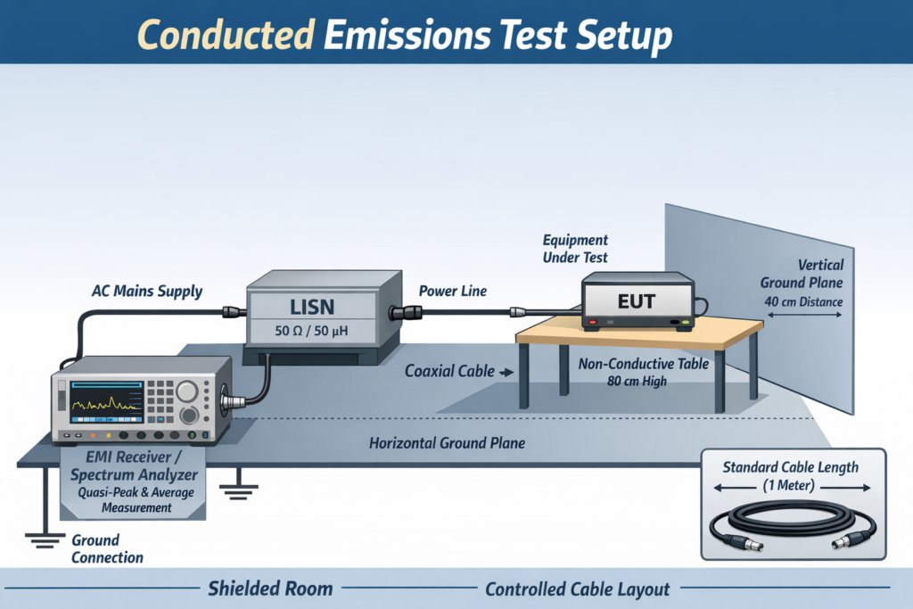
Key configuration rules:
-
- EUT placed on non-conductive table (80 cm high)
- 40 cm from vertical ground plane
- 80 cm from horizontal ground plane
- Cable length controlled (typically 1 meter)
Limit Lines