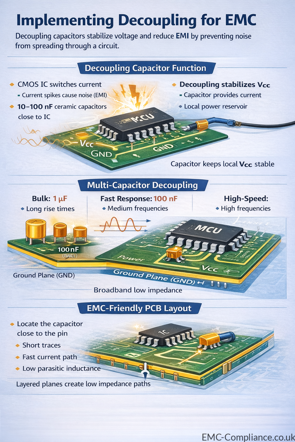
Implementing decoupling in electronic circuits is a fundamental technique in electromagnetic compatibility (EMC) design. As digital systems switch currents rapidly, they generate high-frequency noise and transient voltage disturbances on the power distribution network. Without proper decoupling, these disturbances can propagate through the circuit, causing malfunction, signal integrity problems, and increased electromagnetic emissions. Decoupling capacitors provide a local energy reservoir that stabilizes supply voltages and prevents noise from spreading between components and across the PCB.
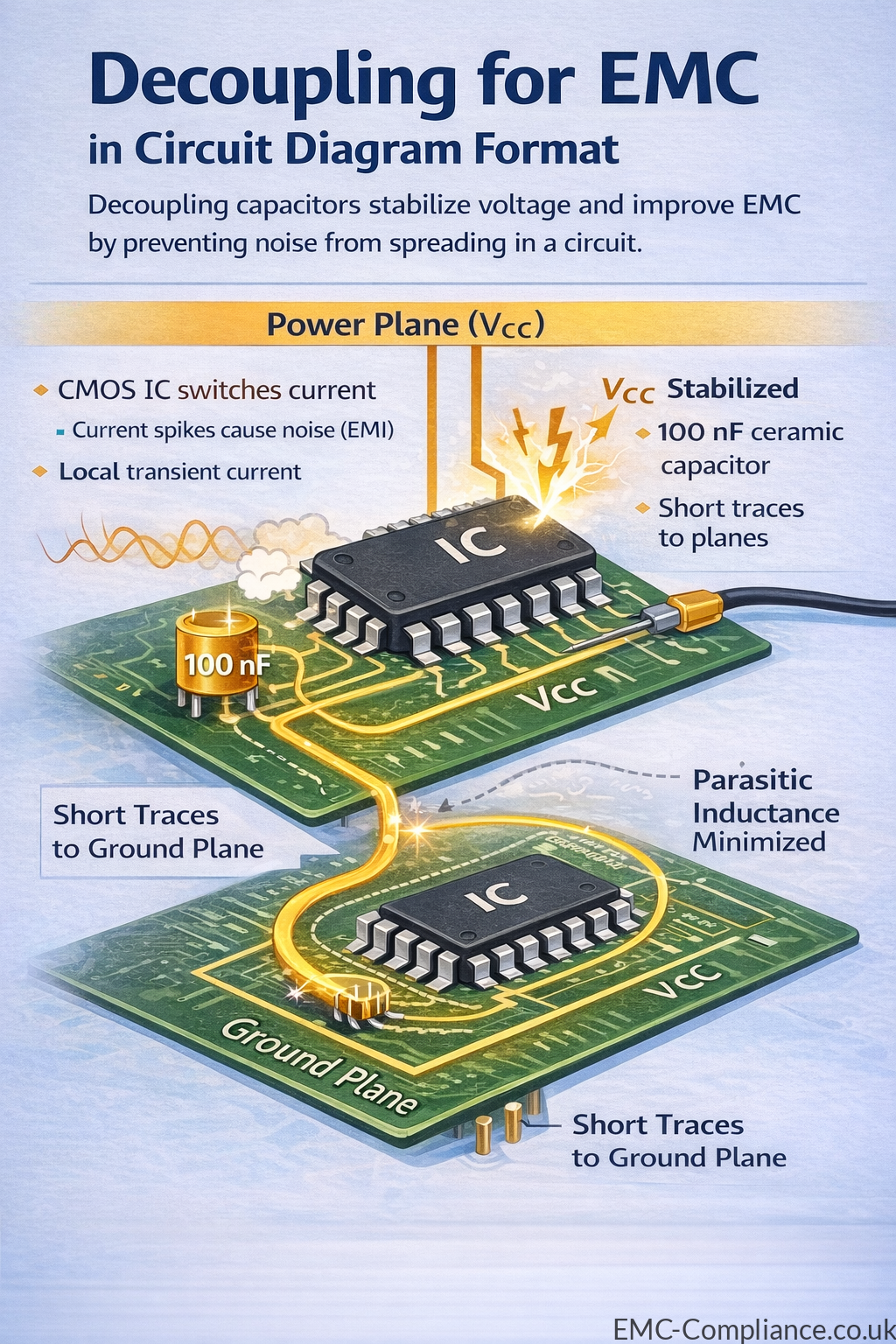
In modern digital electronics, devices such as microcontrollers, FPGAs, processors, and high-speed interfaces switch currents within nanoseconds. Each time an internal logic gate changes state, a brief surge of current is drawn from the power supply. If the power delivery path has significant impedance—due to trace inductance or regulator distance—the voltage at the device pins can momentarily dip or spike. Decoupling capacitors placed close to the power pins supply the required transient current locally, maintaining a stable voltage level and preventing disturbances from coupling into other parts of the circuit.
Effective decoupling design typically uses a combination of capacitor values to cover a wide frequency range. Larger capacitors, often in the range of 1 µF to 10 µF, provide bulk energy storage and support lower-frequency current demands. Smaller capacitors, such as 100 nF or 10 nF ceramic capacitors, respond much faster and suppress high-frequency switching noise generated by digital devices. By placing multiple capacitors in parallel, designers create a broadband low-impedance path between the power rail and ground, which improves the stability of the power distribution network.
The physical placement of decoupling capacitors is just as important as their value. For effective noise suppression, capacitors should be located as close as possible to the integrated circuit’s power and ground pins. Short traces and direct connections to the ground plane reduce parasitic inductance, allowing the capacitor to respond quickly to transient currents. In multilayer PCB designs, placing decoupling capacitors on the same side as the device and connecting them directly to power and ground planes through short vias greatly improves EMC performance.
Decoupling also plays a key role in controlling electromagnetic emissions. High-frequency noise on power rails can radiate through PCB traces, cables, and connectors, contributing to unwanted emissions that may cause a product to fail EMC compliance testing. Properly designed decoupling networks confine high-frequency currents to small local loops, reducing the area through which noise can radiate. This helps ensure that digital systems operate reliably while meeting regulatory standards for electromagnetic compatibility.
In summary, decoupling capacitors are essential components in EMC-conscious circuit design. By stabilizing supply voltages, providing local transient current, and suppressing high-frequency noise, they protect digital electronics from internal disturbances and external interference. Careful selection of capacitor values, strategic placement near device power pins, and integration with a well-designed PCB power distribution network are all critical factors in achieving robust EMC performance.