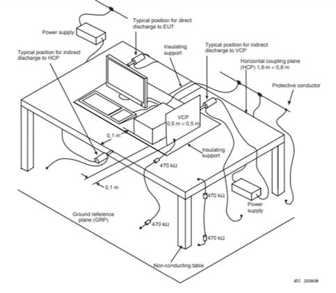
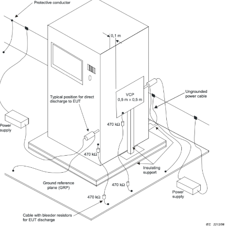
ESD (electrostatic discharge) test setup includes the GRP (ground reference plane), HCP (horizontal coupling plane), VCP (vertical coupling plane), resistance cable (including 2*470kΩ resistors), insulating support, and wood table.
When designing the setup, IEC/EN 61000-4-2 standard should be used a reference for dimensions and measurements.
1 General Layout
2) EFTB Generator
3) Test Levels.
Electrostatic discharges are applied to the EUT at points and surfaces which are normally accessible to the operator under normal operating conditions. These discharges are also applied to the metal coupling planes (HCP, VCP). The voltage levels are increased gradually until the maximum severity level selected is reached. Discharges to the EUT and coupling plane are performed at a minimum of 1sec intervals at each polarity.
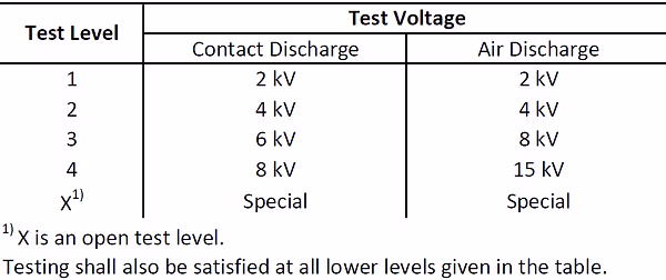
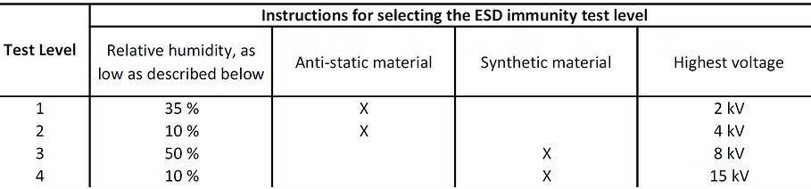
The following table below should help to determine which test level to apply for specific relative humidity levels and materials involved (test levels are specified in the corresponding Product (Family) EMC Standard or Generic EMC Standard).
4) Calibration
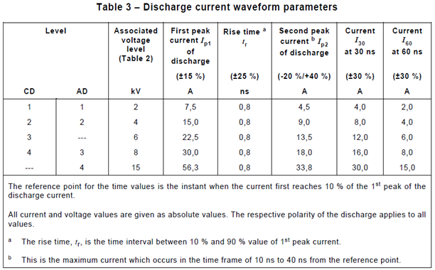
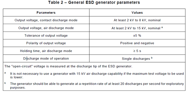
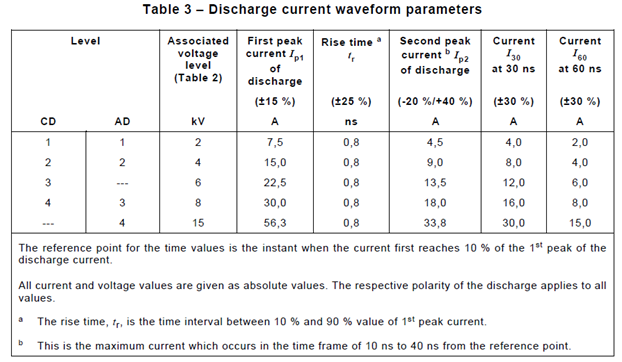
The ESD generator system must be calibrated to ensure the specifications of the tables 2 and 3, below, are met.
ESD generators that can be powered by either mains or battery must have both modes calibrated.
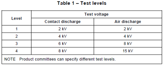
ESD generators shall be calibrated at levels 1-4, in both polarities, as shown in Table 1, below.
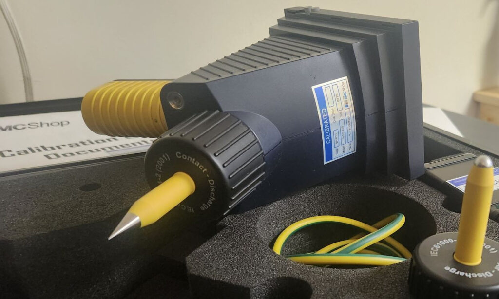
Contact Discharge (CD) calibration shall be performed as follows, with the contact discharge tip mounted. All measured values and a minimum of one discharge current waveform shall be recorded. One recording of the +8.0 kV waveform must be recorded.
Open-Circuit Output Voltage:
Measure the open-circuit voltage of the ESD generator with the discharge switch activated.
Current Waveform:
Complete the following steps and record for each of 5 discharges for positive and negative polarities.
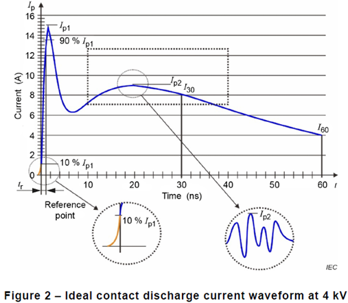
Ip1 1st peak value of the discharge current [A]
Ip2 2nd peak value of the discharge current [A]
I30 value of the current 30 ns after the reference point (10 % of Ip1) [A]
I60 value of the current 60 ns after the reference point (10 % of Ip1) [A]
tr rise time of the current [ns]
Air Discharge (AD), if the contact and air discharge tips are simple conductors with no additional active/passive components, the calibration can be limited to the open circuit voltage measurement at the air discharge tip. This should be done at the maximum AD test voltage. Otherwise, calibration should be performed at one voltage level with the ESD generator in CD mode, but with the AD tip mounted, as follows.
Current Waveform:
Complete the following steps and record for each of the 5 discharges for positive and negative polarities.
Ip1 1st peak value of the discharge current [A]
Ip2 2nd peak value of the discharge current [A]
I30 value of the current 30 ns after the reference point (10 % of Ip1) [A]
I60 value of the current 60 ns after the reference point (10 % of Ip1) [A]
tr rise time of the current [ns]
Equipment required for ESD generator calibration is as follows.
- High-voltage meter capable of measuring 15 kV. A resistive high-voltage divider shall be connected for open-circuit output calibration. The accuracy of this divider shall be +/- 1 % with a minimum resistance specified by the maker of the generator.
- Oscilloscope with a >/= bandwidth of 2.0 GHz and sampling rate of >/= 8 GS/s
- Coaxial current target-attenuator-cable chain with calibrated target
- Attenuator
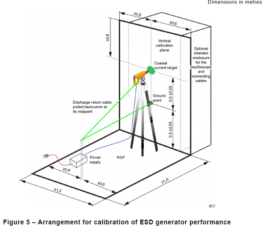
The setup for ESD current waveform calibration is as follows.
Notes:
- The generator shall be installed on a non-conductive support
- The RGP and vertical calibration plane shall be electrically connected
- The ESD generator shall make contact with the center conductor of the target
- The discharge return cable shall be pulled backwards at its middle, forming a triangle, and shall not lie on the RGP or be held
- Any ESD generator external power supply shall be placed on the RGP
- No conductive objects shall be placed in the area of the 1.5m x 1.2m calibration setup
- The power cable to the ESD generator shall be routed along the RGP and calibration plane
5) Air Discharge
Guidance for Air Discharges
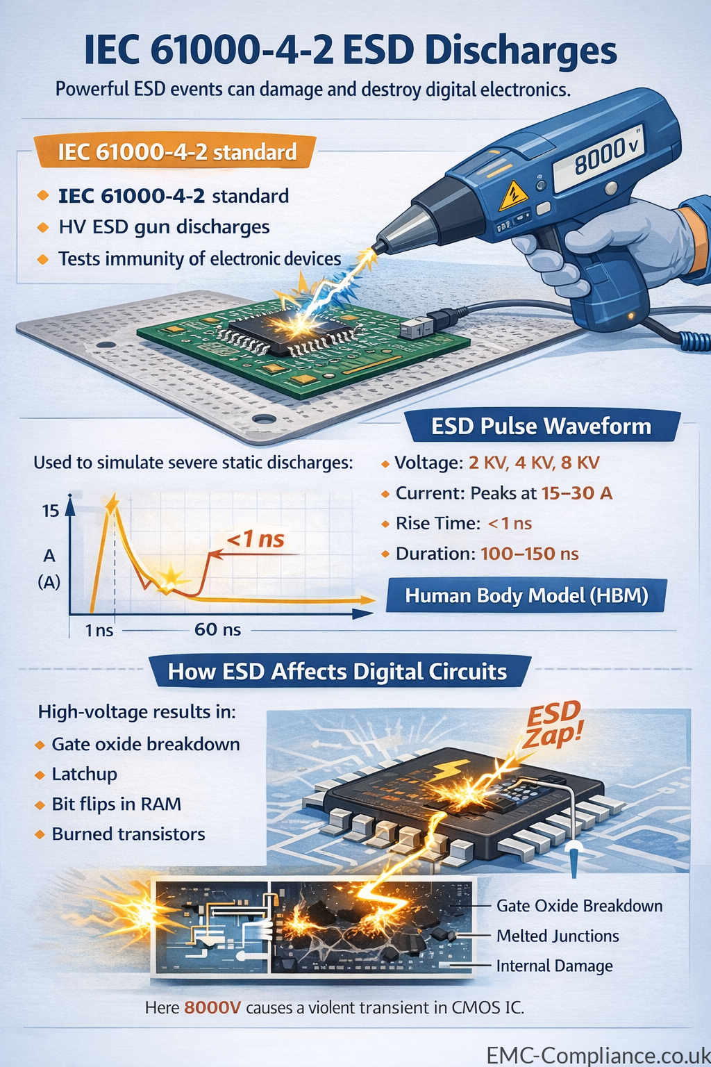
Air discharge testing under IEC 61000-4-2 is used to simulate electrostatic discharge events where a charged object approaches equipment and a spark jumps through the air to the device under test (DUT). Unlike contact discharge, air discharge more closely represents real-world ESD events from human interaction, particularly on non-conductive surfaces such as plastic enclosures, display covers, and keypads.
During air discharge testing, the ESD simulator (ESD gun) is charged to the specified test voltage (commonly ±2 kV, ±4 kV, ±8 kV, and up to ±15 kV depending on product requirements). The rounded air-discharge tip is slowly brought toward the test point until a discharge occurs. The approach speed should be consistent and perpendicular to the surface to ensure repeatability. Because breakdown voltage depends on humidity, temperature, and air gap distance, environmental conditions must be controlled—typically 15–35°C and 30–60% relative humidity.
Test points should include all accessible surfaces and user interface areas that could reasonably be touched during normal operation. Discharges are generally applied at least 10 times per polarity at each test location. Functional performance of the DUT must be monitored continuously to classify results according to performance criteria (A, B, C, or D as defined in the standard). Clear documentation of test levels, environmental conditions, discharge locations, and observed behavior is essential for compliance reporting and certification.
Home – Latest Standards – FCC vs CISPR – Fast Transient Bursts – GDPR – EMC Screen Termination