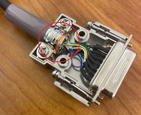
Pigtails
In EMC (Electromagnetic Compatibility) practice, a pigtail refers to a short wire used to connect a cable’s shield to an earth point instead of terminating the shield directly under a connector or EMC gland. While it might seem like a convenient way to ground the cable, pigtails are generally considered poor practice because they compromise the effectiveness of the shield. The main purpose of a cable screen is to provide a continuous low-impedance path for unwanted electromagnetic interference (EMI) to earth. Introducing a pigtail interrupts this continuity and creates an additional point of impedance in the path.
At high frequencies, the impedance of the pigtail can be significant, meaning that EMI may not be effectively diverted to earth. This allows interference to couple into the signal conductors, potentially causing data errors, equipment malfunction, or increased radiated emissions. Pigtails are particularly problematic in industrial environments with motors, drives, and high-frequency switching equipment, where the noise spectrum extends into the MHz range. In these conditions, even short pigtails can act as small antennas, either radiating noise or picking it up from the surrounding environment.
Another issue with pigtails is mechanical reliability. A separate wire connection is more likely to become loose or corroded over time, resulting in intermittent shielding performance. For these reasons, EMC standards such as IEC 61000 and BS EN 50310 recommend direct 360° termination of the cable shield to metal enclosures or connectors. A direct termination under a metal EMC gland provides full circumferential contact, minimizing impedance and ensuring a robust, continuous path to earth.
In summary, while pigtails may appear to offer a quick solution for grounding cable shields, they compromise EMC performance by increasing impedance, reducing shielding effectiveness, and introducing potential mechanical failure points. For reliable EMC performance, cable shields should always be terminated directly under a properly installed metal gland or connector, ensuring a low-impedance, continuous path to earth.
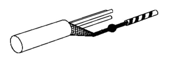
Pigtail Screen
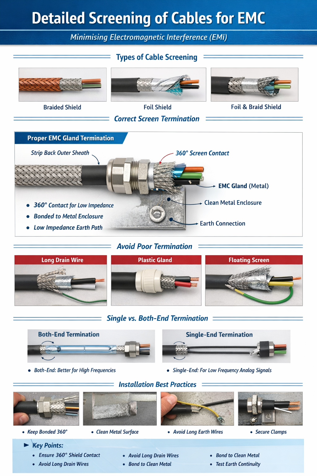
360deg Termination
360° EMC shielding refers to the practice of terminating a cable’s shield in a way that provides full circumferential contact with a conductive surface, such as a metal connector, gland, or enclosure. The concept is fundamental in electromagnetic compatibility (EMC) design because it ensures that the shield can carry unwanted electromagnetic noise directly to earth with minimal impedance. Unlike partial or single-point connections, which leave gaps in the shielding, a full 360° connection provides a continuous path around the entire circumference of the cable, preventing EMI from coupling into the signal conductors.
The effectiveness of 360° shielding becomes increasingly critical at high frequencies, where even small gaps or discontinuities can act as antennas, allowing electromagnetic energy to leak into or out of the cable. By maintaining full contact, the shield acts as a Faraday cage around the conductors, reflecting and diverting high-frequency interference away from sensitive electronics. Proper 360° termination is achieved using metal EMC glands, connector shells, or bonding clamps that compress the cable shield evenly around the circumference, ensuring low impedance and robust mechanical contact.
In addition to improving noise immunity, 360° shielding also enhances regulatory compliance. Standards such as IEC 61000 and BS EN 50310 emphasize the importance of complete shielding contact to minimize emissions and maximize susceptibility protection. A well-implemented 360° shield not only reduces the risk of signal degradation but also mitigates potential issues in industrial environments, such as those caused by motors, variable frequency drives, and high-speed digital circuits.
Finally, from a practical standpoint, 360° shielding eliminates the need for pigtails or single-point connections, which can introduce high impedance and create resonant loops. It also improves long-term reliability, as the continuous mechanical and electrical contact is less prone to loosening or corrosion. In short, 360° EMC shielding is a best-practice method that provides maximum EMI protection, regulatory compliance, and system reliability.
360deg Termination
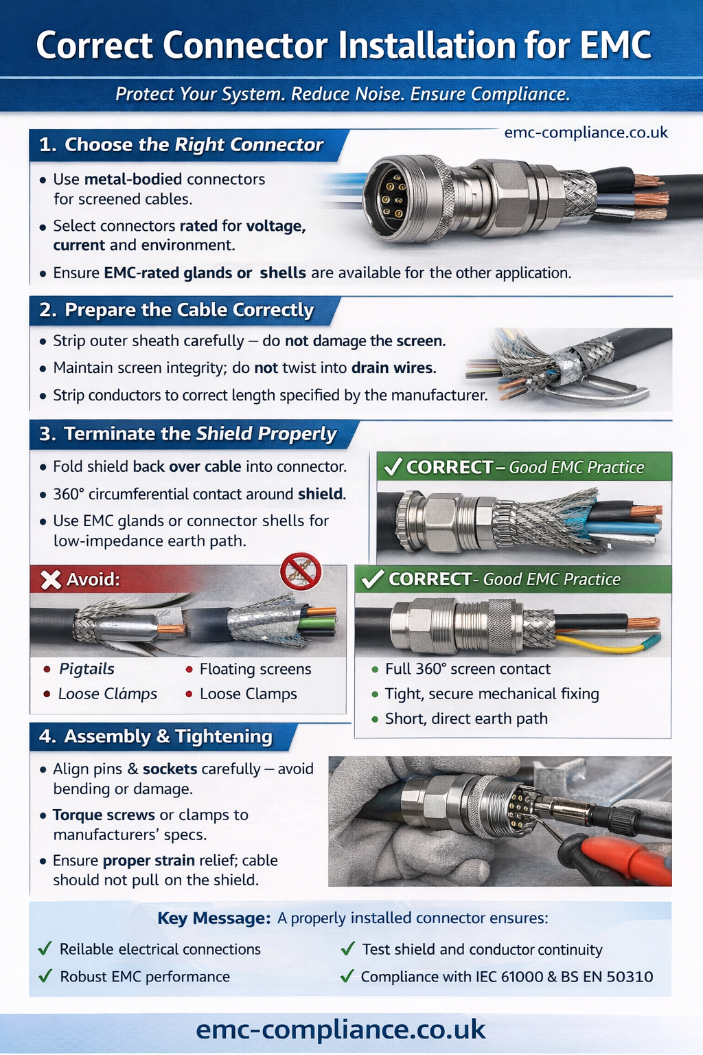
Connector Installation
Proper connector installation is essential for both mechanical reliability and electromagnetic compatibility (EMC). Connectors serve as the interface between cables and equipment, and any mistakes in installation can compromise signal integrity, introduce noise, or even lead to equipment failure. The installation process begins with selecting the right connector type for the application, considering factors such as current rating, environmental protection, shielding requirements, and frequency range. EMC-compliant connectors, typically metal-bodied and capable of 360° screen termination, are preferred in industrial and high-frequency applications.
A critical step in connector installation is the preparation of the cable. The outer sheath must be stripped carefully to expose the screen without damaging it, and the individual conductors must be cut and stripped to the correct length as specified by the connector manufacturer. For screened cables, it is important to maintain the integrity of the screen and avoid twisting it into drain wires. The shield should be folded or clamped under the connector’s metal shell to ensure full 360° contact, providing a low-impedance path to earth and preventing electromagnetic interference (EMI).
During assembly, attention must be paid to torque settings and mechanical alignment. Connector screws, clamps, or glands should be tightened according to manufacturer specifications to ensure proper shielding contact and strain relief. Incorrect tightening or misalignment can lead to intermittent connections, increased contact resistance, or partial shielding, which significantly reduces EMC performance. For circular or D-type connectors, care should be taken to align pins and sockets correctly to prevent bending or damage during mating.
Finally, inspection and testing are essential. After installation, connectors should be visually inspected to ensure the shield is fully engaged, there is no exposed conductor, and the mechanical clamp is secure. Where possible, continuity tests should be performed on the shield and signal conductors to verify correct installation. Following these procedures ensures connectors not only provide reliable electrical connections but also maintain robust EMC protection, reducing the risk of noise coupling and improving overall system performance.