Common versus differential mode
In electrical and electronic systems, signals and electrical noise can travel through conductors in different ways. Two of the most important concepts used to describe these current and voltage paths are common mode and differential mode. Understanding the difference between them is essential for engineers, technicians, and students working with power systems, communication networks, electronic circuits, electromagnetic compatibility (EMC), and signal transmission. These concepts help explain how useful signals are carried between devices and how unwanted interference affects system performance.
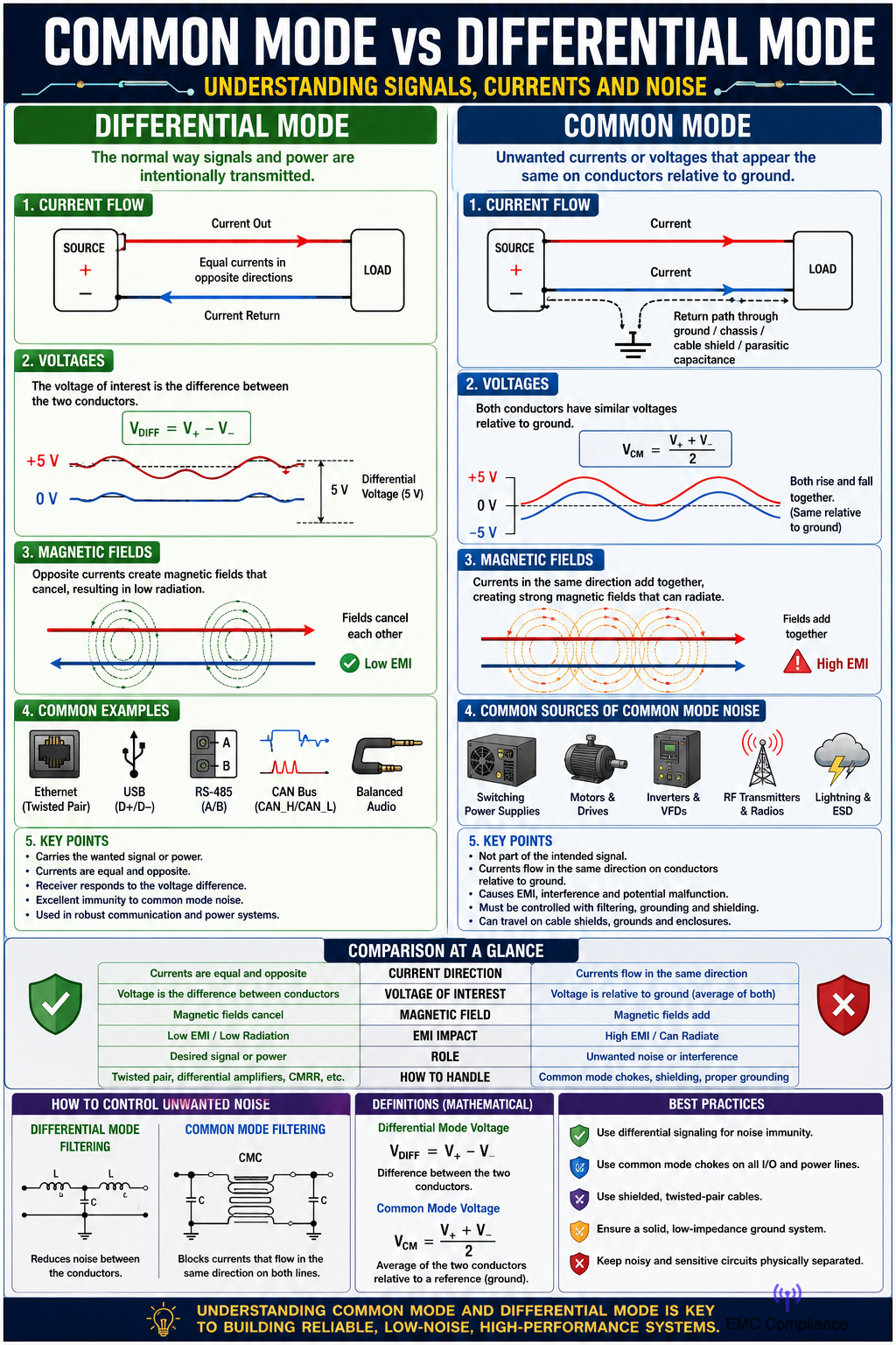
Differential mode refers to a condition where current flows in opposite directions through two conductors. One conductor carries current toward the load while the other conductor carries an equal amount of current back toward the source. The voltage of interest is measured between the two conductors. This is the normal operating mode for most electrical and electronic circuits because it is how power and information are intentionally transmitted. For example, in a simple battery-powered circuit, current leaves the positive terminal, passes through the load, and returns through the negative terminal. This current path represents differential mode operation.
The term “differential” comes from the fact that the receiver or measuring device responds to the difference in voltage between the two conductors. If one conductor has a voltage of +5 V and the other has a voltage of 0 V, the differential voltage is 5 V. In communication systems, data is often transmitted using differential signaling because the receiver only cares about the voltage difference between the lines rather than their absolute voltages relative to ground.
Common mode, on the other hand, occurs when currents flow in the same direction on multiple conductors relative to a common reference, usually ground or chassis. Instead of one conductor carrying current out and another carrying it back, the conductors carry similar currents simultaneously. These currents often return through unintended paths such as earth ground, cable shields, equipment enclosures, or parasitic capacitances. Common mode currents are frequently associated with electromagnetic interference (EMI) and noise problems.
A useful way to visualize common mode current is to imagine two wires running together. In differential mode, current travels down one wire and returns through the other wire. The magnetic fields generated by the currents tend to cancel each other because they flow in opposite directions. In common mode, both wires carry current in the same direction. Since the currents reinforce each other rather than cancel, they can create stronger electromagnetic fields and radiate unwanted interference into the surrounding environment.
One of the major concerns in modern electronic equipment is common mode noise. This noise can be generated by switching power supplies, motors, inverters, radio transmitters, lightning events, and many other sources. Common mode noise often appears equally on multiple conductors relative to ground. Since it is not part of the intended signal, it can interfere with circuit operation, reduce signal quality, and cause electromagnetic compatibility issues.
Differential mode noise is another form of interference, but it behaves differently. Differential noise appears as a voltage difference between two conductors. Since the noise exists directly in the signal path, it can distort the intended signal or power waveform. Differential noise is often generated by switching devices, power converters, and rapidly changing currents within circuits. Unlike common mode noise, differential noise follows the same path as the useful signal.
Communication systems frequently take advantage of differential signaling because of its excellent noise rejection properties. Technologies such as Ethernet, USB, RS-485, CAN bus, and many high-speed data interfaces transmit information using differential pairs. When external noise affects both conductors equally, the receiver largely ignores it because the voltage difference between the conductors remains unchanged. This ability to reject common mode disturbances improves signal integrity and reliability.
An important parameter in differential communication systems is the Common Mode Rejection Ratio (CMRR). CMRR measures how effectively a receiver, amplifier, or circuit can reject common mode signals while accurately amplifying differential signals. A high CMRR means the device is very good at ignoring unwanted common mode noise. Instrumentation amplifiers and differential amplifiers are specifically designed to provide high common mode rejection.
In power electronics, both common mode and differential mode noise must be controlled to meet EMC regulations. Engineers often use filters to suppress these unwanted currents. A differential mode filter is designed to reduce noise appearing between conductors. It typically uses inductors and capacitors arranged to block high-frequency differential currents while allowing normal power flow.
Common mode filters operate differently. A common mode choke is one of the most common solutions. It consists of two windings on a shared magnetic core. Differential currents flowing in opposite directions create magnetic fields that cancel each other, allowing the desired signal to pass with little impedance. Common mode currents flowing in the same direction create reinforcing magnetic fields, resulting in high impedance that suppresses the unwanted noise.
Grounding practices also play a significant role in controlling common mode effects. Poor grounding can create voltage differences between equipment, encouraging common mode currents to flow through cable shields and unintended paths. Proper grounding, shielding, and cable routing help minimize these currents and reduce electromagnetic interference.
Shielded cables are another important method for reducing common mode noise. The conductive shield provides a low-impedance path for interference currents and prevents external electromagnetic fields from coupling into signal conductors. In many industrial and communication applications, shielded twisted-pair cables combine the benefits of differential signaling and shielding to achieve excellent noise immunity.
The distinction between common mode and differential mode becomes especially important when troubleshooting electrical systems. If interference appears equally on all conductors relative to ground, the issue is likely common mode in nature. If the interference exists between conductors and directly affects the signal voltage difference, it is likely differential mode noise. Correctly identifying the type of noise helps engineers select the appropriate filtering and mitigation techniques.
From a mathematical perspective, differential voltage is calculated as the voltage difference between two conductors. Common mode voltage is calculated as the average voltage of the conductors relative to a common reference point. These calculations allow engineers to separate a complex signal into its differential and common mode components for analysis and design purposes.
Differential mode and common mode describe two fundamentally different ways that currents and voltages can exist within electrical systems. Differential mode represents the intended transfer of power or information through opposite current flow and voltage differences between conductors. Common mode represents voltages or currents that appear simultaneously on conductors relative to a common reference, often resulting in unwanted noise and electromagnetic interference. Understanding these concepts is essential for designing reliable electronic systems, improving signal integrity, reducing EMI, and ensuring compliance with electromagnetic compatibility standards.
Common Mode on Power Supplies
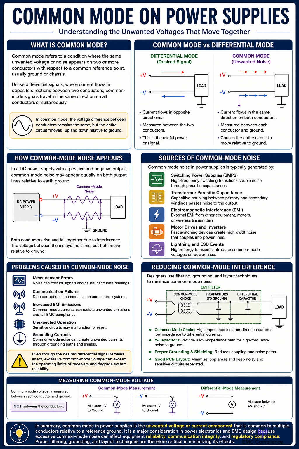
In power supply systems, common mode refers to a condition where the same unwanted voltage or noise appears on two or more conductors with respect to a common reference point, usually ground or chassis. Unlike differential signals, where current flows in opposite directions between two conductors, common-mode signals travel in the same direction on all conductors simultaneously.
For example, in a DC power supply with a positive and negative output, common-mode noise may appear equally on both output lines relative to earth ground. If both conductors rise and fall together due to electrical interference, the voltage difference between them remains unchanged, but the entire circuit “moves” relative to ground. This type of noise is often generated by switching power supplies, electromagnetic interference (EMI), lightning disturbances, motor drives, or capacitive coupling from high-frequency switching devices.
Common-mode noise can create several problems in electronic equipment. Sensitive circuits may experience measurement errors, communication failures, increased electromagnetic emissions, or unexpected operation. In industrial environments, common-mode voltages can couple into signal cables and cause data corruption in control systems, instrumentation, and communication networks. Even though the desired differential signal remains intact, the common-mode component can exceed the operating limits of receivers or create unwanted currents through grounding paths.
A significant source of common-mode noise in modern switched-mode power supplies (SMPS) is the high-frequency switching action of transistors. During switching transitions, parasitic capacitances inside transformers and other components allow noise currents to flow from the primary side to the secondary side. These currents can then appear as common-mode voltages on the output wiring. Because switching frequencies can range from tens of kilohertz to several megahertz, the resulting noise can be difficult to suppress.
To reduce common-mode interference, designers commonly use common-mode chokes, EMI filters, shielding, proper grounding techniques, and Y-capacitors. A common-mode choke is particularly effective because it presents high impedance to currents flowing in the same direction on both conductors while allowing normal differential currents to pass with minimal restriction. This helps attenuate common-mode noise without affecting the intended power delivery.
When measuring common-mode voltage, the measurement is typically taken between the conductors and ground rather than between the conductors themselves. This distinguishes common-mode quantities from differential-mode quantities, which are measured directly between the conductors. Understanding this difference is essential when troubleshooting power quality issues, EMC compliance problems, and power supply noise performance.
Common mode in power supplies is the unwanted voltage or current component that is common to multiple conductors relative to a reference ground. It is a major consideration in power electronics and EMC design because excessive common-mode noise can affect equipment reliability, communication integrity, and regulatory compliance. Proper filtering, grounding, and layout techniques are therefore critical in minimizing its effects.