TEM Cell RF Power Calculator
TEM Cell RF Power Calculator – User Instructions
Purpose
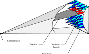
This calculator determines the RF power required to generate a specified electric field level inside a TEM (Transverse Electromagnetic) cell.
It can be used for EMC pre-compliance testing, RF immunity testing calculations, and estimating RF amplifier requirements.
The calculator supports two calculation methods:
- TEM Height / Impedance Method
- Calibration Factor Method
1. Select Calculation Method
TEM Height / Impedance Method
Use this method when the TEM cell physical dimensions are known.
The calculation uses:
- Desired electric field level
- TEM cell height (septum spacing)
- Characteristic impedance (normally 50 Ω)
- System losses
This method provides an estimate of the required RF power.
Calibration Factor Method
Use this method when the TEM cell has been calibrated and the manufacturer provides a field calibration factor.
The calibration factor is normally specified as:
V/m per √W
This is the preferred method for accurate EMC testing because it accounts for the actual field distribution and losses of the TEM cell.
Input Parameters
Desired Field Level
Enter the required electric field strength.
Examples:
- 10 V/m
- 100 V/m
- 1 kV/m
Select the correct unit:
- V/m (volts per metre)
- kV/m (kilovolts per metre)
TEM Cell Height
Enter the distance between the TEM cell septum and the outer conductor.
Select the correct unit:
- metres (m)
- centimetres (cm)
- millimetres (mm)
Example:
A septum spacing of 100 mm should be entered as:
- Value: 100
- Unit: mm
Z Impedance
Enter the characteristic impedance of the TEM cell.
Most TEM cells use:
50 Ω
Only change this value if the TEM cell has a different characteristic impedance.
Calibration Factor
Enter the calibration factor supplied with the TEM cell.
Typical format:
V/m per √W
Example:
If the calibration report states:
10 V/m per √W
enter:
10
This value is only required when using the Calibration Factor Method.
System Losses
Enter all losses between the RF amplifier output and the TEM cell input.
Include:
- RF cable loss
- Connector losses
- Adaptor losses
- Switch or attenuator losses
- Other insertion losses
Enter the total loss in dB.
Example:
Cable loss:
- 1.5 dB
Connector loss:
- 0.5 dB
Total system loss:
2 dB
Amplifier Headroom Margin
This allows additional RF power reserve to ensure the amplifier can achieve the required field level.
Typical values:
- 0 dB = no reserve
- 3 dB = double power capability
- 6 dB = four times power capability
A value of 3 dB is commonly used for practical testing.
Understanding the Results
The calculator provides:
Required Voltage
The approximate RF voltage required inside the TEM cell.
TEM Cell Power
The theoretical power needed at the TEM cell input before cable and system losses.
Total Loss + Margin
The additional power allowance required to compensate for:
- System losses
- Amplifier headroom
RF Generator Power Required
The final RF power level that should be available from the RF amplifier or generator.
The result is displayed in:
- Watts (W)
- dBm
Example Calculation
Input:
- Desired field: 100 V/m
- TEM height: 100 mm
- Impedance: 50 Ω
- System losses: 3 dB
- Amplifier margin: 3 dB
The calculator determines the RF power required after allowing for the additional system losses and amplifier reserve.
Notes
This calculator provides an engineering estimate. For certified EMC testing, always use the calibration data supplied with the specific TEM cell.
The calibration factor method is recommended when performing measurements to EMC standards because it accounts for:
- TEM cell construction
- Field uniformity
- Frequency response
- Real-world insertion losses
Always verify the final field strength using the appropriate calibrated field probe.