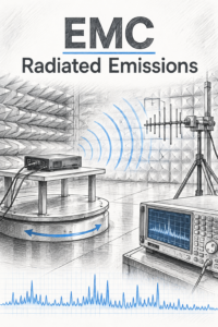
Test setup for Radiated Emissions for EN55032:2015+A1:2020 is as
Introduction to Radiated Emissions Testing
Radiated emissions testing is an essential part of electromagnetic compatibility (EMC) assessment for multimedia equipment. The purpose of the test is to measure the electromagnetic energy emitted by electronic and electrical equipment and determine whether these emissions remain within the limits specified by EN 55032.
Unwanted electromagnetic emissions can originate from a variety of sources within a product, including high-speed digital circuits, processor clocks, switching power supplies, display interfaces, data cables and internal communication buses. These emissions can propagate through the air and potentially interfere with the operation of nearby electronic equipment, wireless receivers and communication systems.
EN 55032 defines the requirements and measurement methods used to assess radiated emissions from multimedia equipment within its scope. The applicable limits and test conditions depend on the equipment classification, the frequency range being assessed and the relevant requirements of the standard.
Radiated Emissions Test Environment
Radiated emissions measurements are normally performed in a controlled electromagnetic test environment to minimise interference from external radio signals and reflections from surrounding objects. Common test environments include a semi-anechoic chamber, a fully anechoic chamber or an appropriately validated open-area test site.
A semi-anechoic chamber typically incorporates an electrically conductive ground plane and RF-absorbing material on the walls and ceiling. This arrangement provides a controlled measurement environment while allowing the equipment under test (EUT) to be positioned above the ground plane in a representative configuration. The chamber helps reduce unwanted reflections and external interference, improving the repeatability and reliability of the measurements.
The test arrangement must meet the relevant site validation, measurement distance and environmental requirements specified by the applicable edition of EN 55032. A three-metre or ten-metre measurement distance may be used, depending on the facility, equipment and applicable test requirements.
Equipment Under Test (EUT) Configuration
The equipment under test is configured to represent its intended operating conditions. This is an important part of the test because radiated emissions can vary significantly depending on the operating mode, connected peripherals, cable arrangement and activity of internal circuits.
Before measurements begin, the EUT is placed on the appropriate support or turntable, with its associated cables and auxiliary equipment arranged in accordance with the applicable test requirements. Where relevant, the setup includes power supplies, network connections, external displays, data cables and other peripherals needed to exercise the product’s normal functions.
The equipment is operated in representative modes that are likely to produce significant emissions. This may include active data transfer, processing, display operation, communication activity or other functions relevant to the product. The objective is to identify operating conditions that produce the highest emissions, rather than relying on a single arbitrary operating state.
Cable routing and equipment positioning are particularly important. Changes to cable length, orientation or placement can affect the measured emission levels, so the arrangement should be documented and maintained consistently throughout the test.
Measurement Antenna and Test Instrumentation
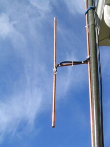
Radiated emissions are measured using a suitable antenna connected to an EMI receiver or an appropriate spectrum analyser configured for compliance measurements. The antenna converts the electromagnetic field radiated by the EUT into an electrical signal that can be measured across the required frequency range.
For typical EN 55032 radiated emissions measurements, the test frequency range extends from 30 MHz to 1 GHz and, where required by the equipment and applicable requirements, above 1 GHz. The upper frequency limit depends on the relevant provisions of the standard, including the internal clock frequencies and other criteria applicable to the EUT.
The antenna is positioned at the prescribed measurement distance from the EUT. Measurements are generally taken with the antenna in both horizontal and vertical polarisation to capture emissions with different field orientations.
An EMI receiver or compliance-grade measurement system applies the specified measurement bandwidths, detector functions and other receiver settings. These settings are important because the measured level can differ depending on the detector and measurement bandwidth used. The test system must be appropriately calibrated, and the measurement site and instrumentation must be suitable for the frequency range being assessed.
Turntable Rotation and Antenna Height Search
A key part of radiated emissions testing is identifying the orientation that produces the highest measured emission level. The EUT is rotated through the required range of orientations, commonly using a motorised turntable, while the measurement system monitors emissions across the relevant frequencies.
For measurements using a semi-anechoic chamber, the antenna height is adjusted over the range specified by the applicable test method. This helps identify the antenna position at which the received field strength is greatest. The combination of EUT rotation, antenna height adjustment and horizontal and vertical antenna polarisation provides a systematic way of finding the maximum radiated emissions.
An initial scan is often used to identify frequencies of interest. These emissions are then investigated using the prescribed final measurement procedure, with particular attention paid to signals approaching or exceeding the applicable limits.
This process helps ensure that the assessment considers the most significant emissions produced by the equipment rather than relying on measurements taken from only one position or orientation.
Assessment Against EN 55032 Limits
The measured emissions are compared with the applicable radiated disturbance limits specified in EN 55032. The relevant limits depend on factors such as whether the equipment falls within Class A or Class B and the frequency range being assessed.
Class B requirements are generally intended for equipment suitable for use in residential environments, where protection of radio reception is particularly important. Class A requirements apply to equipment intended for use in other environments as defined by the standard, and the permitted emission levels are generally less restrictive than those for Class B.
Measurement results must be assessed using the appropriate units, detector requirements and limits for the relevant frequency range. Measurement uncertainty and the applicable compliance decision procedure must also be considered when interpreting the results.
Where an emission approaches or exceeds a limit, further investigation may be required to identify its source. Potential corrective measures include improving cable shielding, modifying PCB layout, reducing common-mode currents, improving enclosure bonding or introducing suitable filtering. Any changes must then be verified through further testing.
Importance of a Repeatable Test Setup
A repeatable radiated emissions test setup is fundamental to producing reliable EMC results. Small changes to cable placement, equipment orientation, operating mode or measurement configuration can influence the measured emissions and potentially affect the compliance outcome.
For this reason, the test arrangement, EUT configuration, operating conditions, antenna polarisation, measurement distance and relevant instrumentation settings should be recorded. Maintaining this information allows measurements to be repeated during product development, design modifications and formal compliance assessment.
Radiated emissions testing to EN 55032 therefore provides more than a simple pass-or-fail measurement. It helps engineers understand how a product interacts electromagnetically with its surroundings, identify potential interference mechanisms and develop effective design improvements before the equipment is placed on the market.
Summary
Radiated emissions testing to EN 55032 is a structured measurement process designed to assess the electromagnetic disturbances emitted by multimedia equipment. By using a controlled test environment, representative operating conditions, calibrated measurement instrumentation and systematic antenna and turntable positioning, engineers can identify the highest emissions and compare them against the relevant requirements.
A well-designed test setup supports repeatable measurements, effective troubleshooting and greater confidence in the EMC performance of the finished product.