What is Radiated Emissions Testing?
A simple definition of Radiated Emissions is “In the field of EMC, the term Radiated Emissions refers to the unintentional release of electromagnetic energy from an electronic device or apparatus. Any electronic device may generate Electromagnetic fields that unintentionally propagate away from the device’s structure. “
Emissions are inherent to the switching voltages and currents within any digital circuit. For EMC, the question is how much energy these emissions have and are they under the limit line.
Radiated Emissions Test Methods
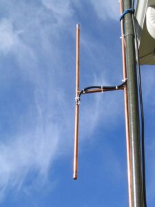
Radiated Emissions tend to be directional, so within the test environment the antenna height will be adjusted between 1 and 4 meters and the turn table is rotated every 45 degrees with the antenna in H and V to maximise the emissions.
The receiving antenna picks up both direct signals from the EUT and multi path reflections i.e. signals bouncing from the ground plane and walls of the screened room. To minimise these reflections the screened room is filled with anechoic foam, this helps absorb and stop these reflections.
Within the test facility the EUT is measured in the frequency range as described in the test specification used. Signals of interest i.e. close to the limit line will be maximised and measured using a quasi-peak detector.
Radiated Emissions Test Sites
There are two types of testing sites, them being:
Open Area Test Site (OATS)
These are commonly constructed to comply with CISPR-16. The distance between the receiving antenna and the EUT can be either 3, 10 or 30m, this is to ensure the equipment under test is being measured in the far field.
The site consists of a ground plane which is earthed, the antenna mast that can measure between 1 to 4 meters and the EUT in the protective non-conductive hut.
Measurements are performed in the screened room or SAR before going to the open area test site, this is to ensure all signals have been measured and maximised as they may be masked by ambient signals on the OATS.

Semi Anechoic Chamber (SAR)
The Semi Anechoic Chamber (SAR) is just like the OATS but the equipment is fully contained within a metal room stopping outside signals from entering. The room is lined with RAM or anechoic foam to limit and stop multi path reflection, this allows for direct signals to be received from the EUT.

Radiated Emissions Limits
Below you will see an example of a radiated emissions measurement with a Class A limit line (in red) for BS EN55032:2015. Limit lines vary depending on the environment they are intended for and standard used i.e. BS EN55011 and BS EN55032.

What Frequency Ranges are Measured
The frequency range of a measurement depends on the highest clock speed in the device. As you can see below the highest clock speed within the EUT to highest measured frequency.

So if my equipment had a clock speed of 200MHz I would have to test from 30MHz to 2GHz.
Conducted Emissions
Conducted emissions is a quite easy and simple test, as you can see from the picture below the EUT (Equipment Under Test) is sat on a non-conductive table 0.8m above the ground reference plane (floor).
The EUT must be placed 0.4m from the wall of the chamber with the LISN (line impendence stabilisation network) 0.8m away.
The EUT plugs into the LISN via a mains cord 1m in length, if the cable can not be shortened then this shall be non-inductively bungled.
The receiver is then connected to either L1 (Live) or L2 (Neutral) depending which line you are measuring.
The EUT is normally plugged into the LISN via a three pin plug if single phase.

Interface sources within circuits of power supplies are coupled on to the main lead. Interference may also be coupled either inductively or capacitively from another cable within the unit onto the power lead.
The resulting interference may appear as differential mode (between live and neutral, or between signal wires) or common mode (between live/neutral signal and earth) or as a mixture of both. For signal and control lines, only common mode currents are of interest. For the main port, the voltage between live and earth and between neutral and earth at the far end of the mains cable are measured. Differential mode emissions are normally associated with low frequency switching noise from the power supply, while common-mode emissions can be due to the higher frequency switching components, internal circuit sources or inter-cable coupling.
Coupling paths
The equivalent circuits for a typical product with switch mode PSU. Differential mode current IDM generated at the input of the switching PSU is measured as an interference voltage across the load impedance of each line with respect to earth at the measurement point. Higher frequency switching noise components V Nsupply are coupled through CC the coupling capacitance between primary and secondary of the isolating transformer, to appear between L/N and E on the mains cable, and Cs to appear with respect to the ground plane. Circuit ground noise VNcct (digital noise and clock harmonics) is referred to ground by Cs and coupled out via signal cables as Icmsigor via the safety earth as Icme.
The problem in a real situation is that all these mechanisms are operating simultaneously, and the stray capacitance Cs are widely distributed and unpredictable, depending heavily on proximity to other objects if the case is unscreened.