1. Introduction
On the 11th of December 2023 EN 55032:2015, with amendments, was withdrawn and superseded by EN 55032:2015+A1:2020
Direct extracts showing the differences between EN 55032:2015 +A11:2020 & EN 55032:2015 +A1:2020 are shown in Annex A.
All products that were considered for this GAP analysis have been tested by competent third parties who carry UKAS accreditation to the original standard which the products were tested to.
EN 55032:2015+A1 supersedes EN 55032:2015+A11 and contains the following differences
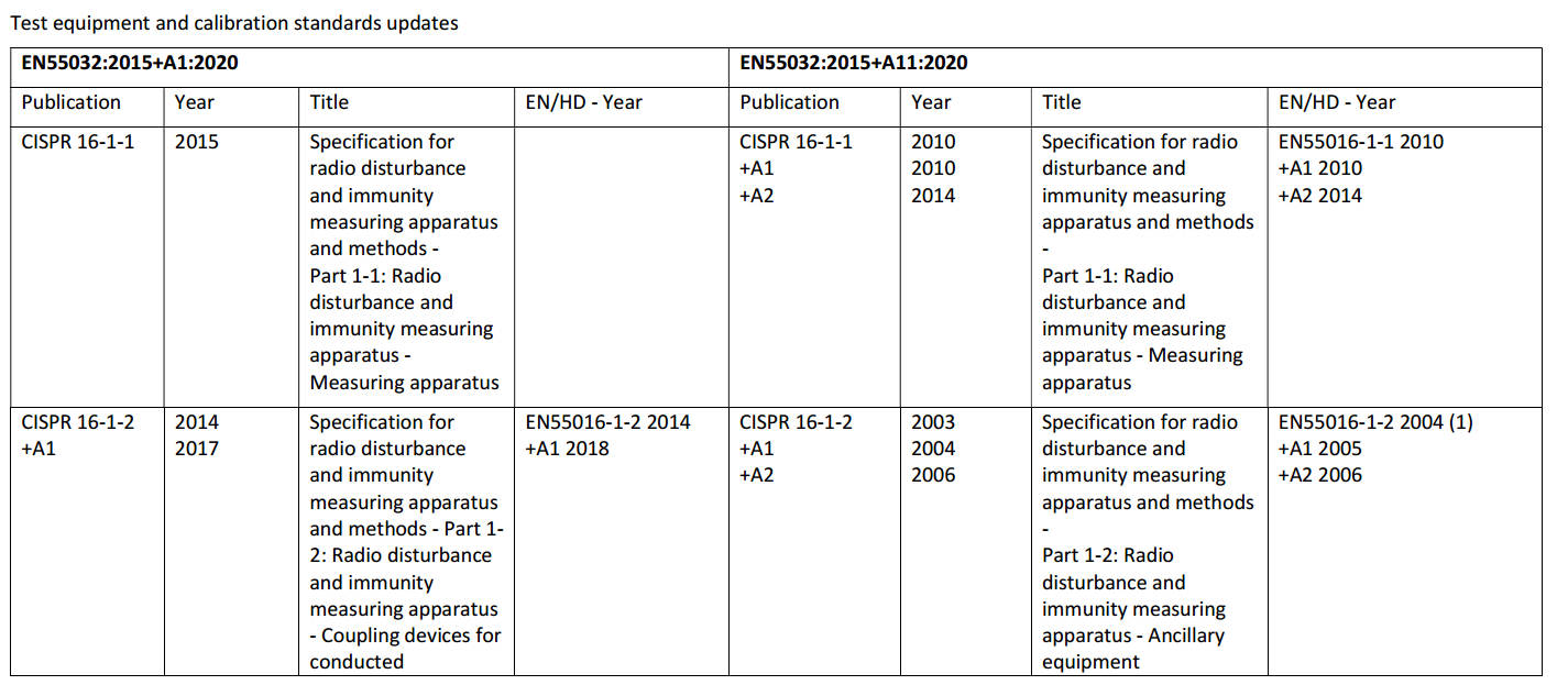
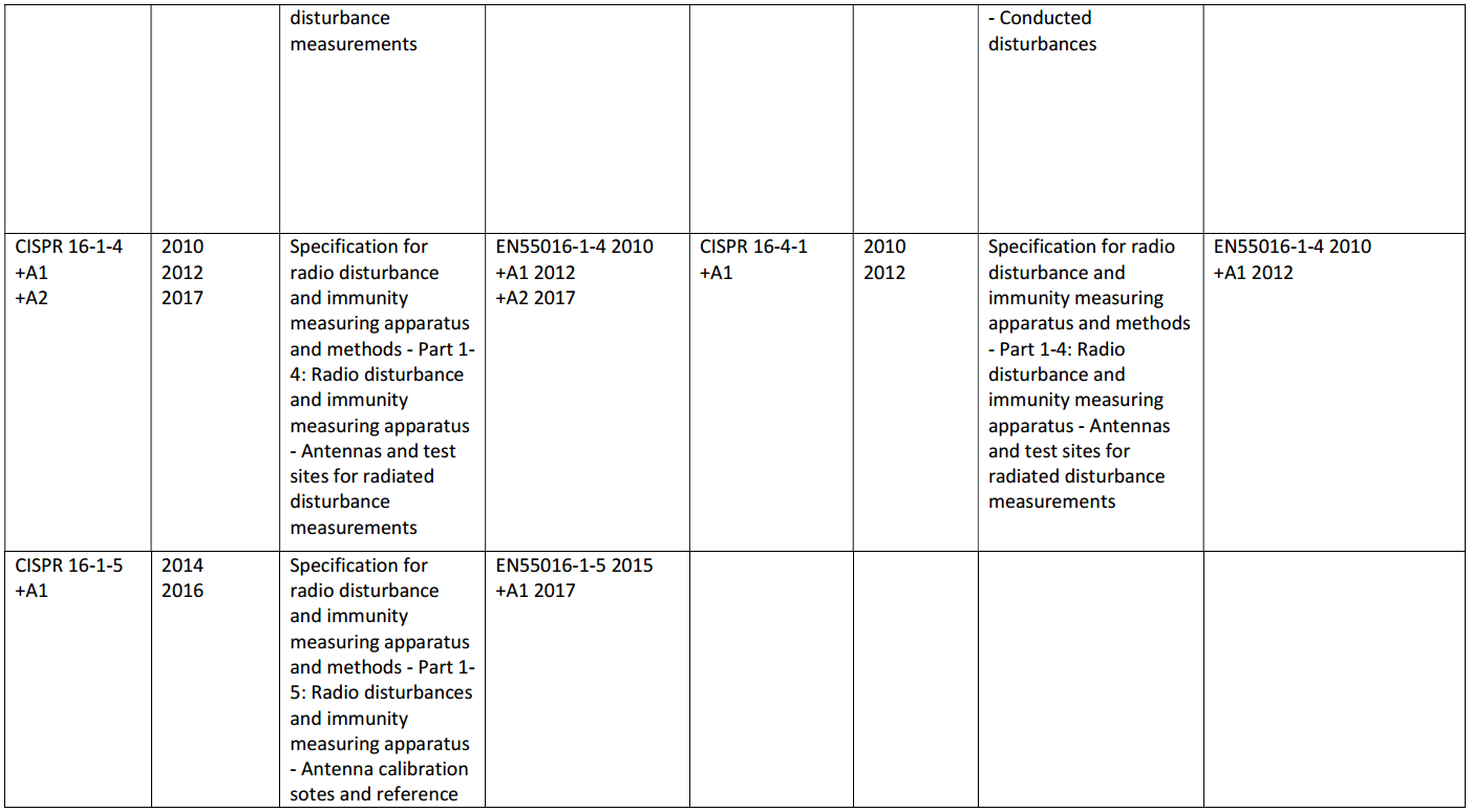
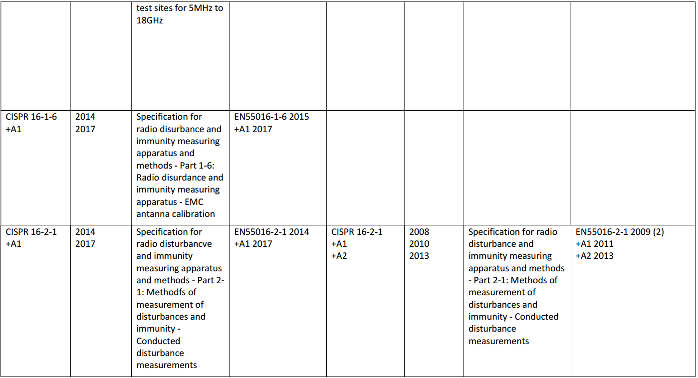
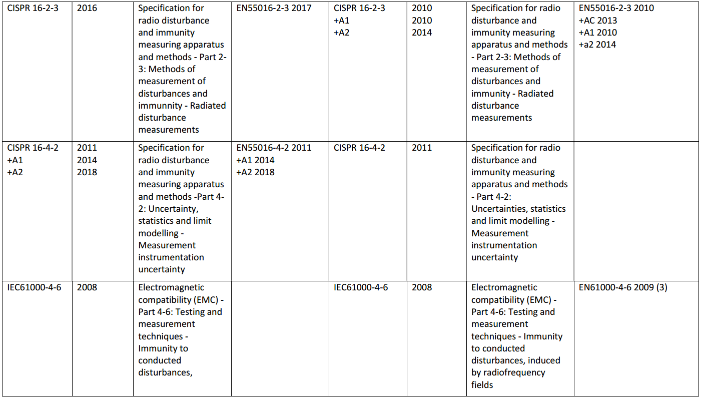
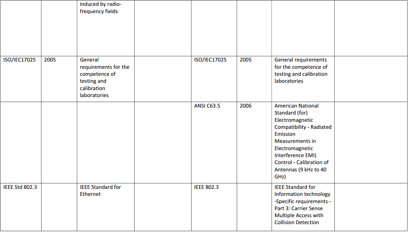
– Test equipment and calibration standard updates
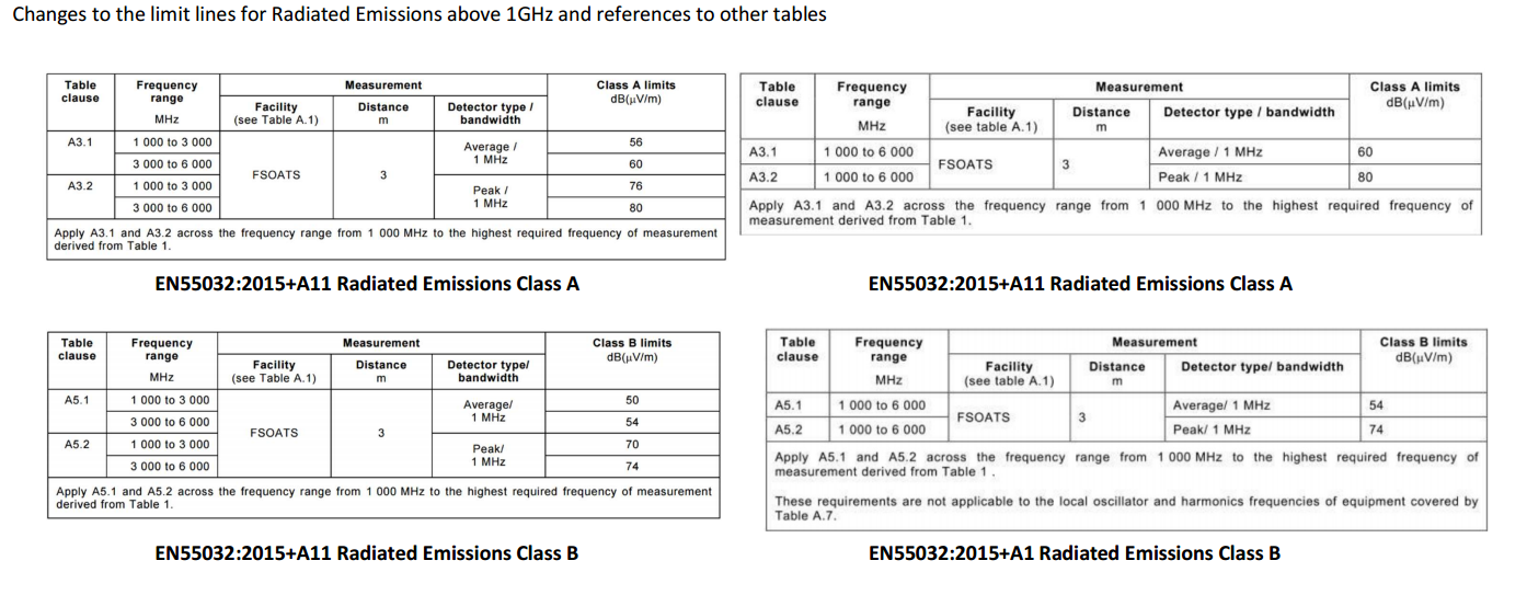
– Changes to the limit lines for Radiated Emissions above 1GHz and references to other tables
– Changes to calibration of antennas for radiated emissions
– Maintenance items are addressed to improve testing of MME
– Methods of exercising displays and video ports updates
1.1 Discussion of Differences
1.2.1 Test equipment and Calibration standard updates
Updated standards contained within Annex ZA are for test equipment and calibration; this is not applicable to manufactures as all standards relate to the test facility.
All updated standards are referenced throughout EN55032:2015+A1:2020
1.1.2 Changes to the limit lines for Radiated Emissions above 1GHz.
There are changes to the limit lines for tables A.3 and A.5, radiated emissions above 1GHz. Between 1 to 3GHz the Limit line is 4dBuV higher.
Table A.5 has had an additional reference placed into the foot notes, this refers to table A.7 and states – These requirements are not applicable to the local oscillator and harmonics frequencies of equipment covered by Table A.7. Table A.7 refers to the requirements of outdoor units of home satellite receiver systems.
1.1.3 Changes to calibration of antennas for radiated emissions
EN 55032:2015+A11 C2.2.2 refers to the procedures within ANSI C63.5 for calibration in free space. EN 55032:2015+A1 has changed, the test laboratory should have antennas calibrated using methods defined in CIPSR 15-1-6:2014/AMD:2017 which emulate those of ANSI C63.5 using the calibration facilities defined in CISPR 16-1-5:2014/AMD1:2016.
1.1.4 Maintenance items are addressed to improve the testing of MME.
A.2 – Requirements for radiated emissions
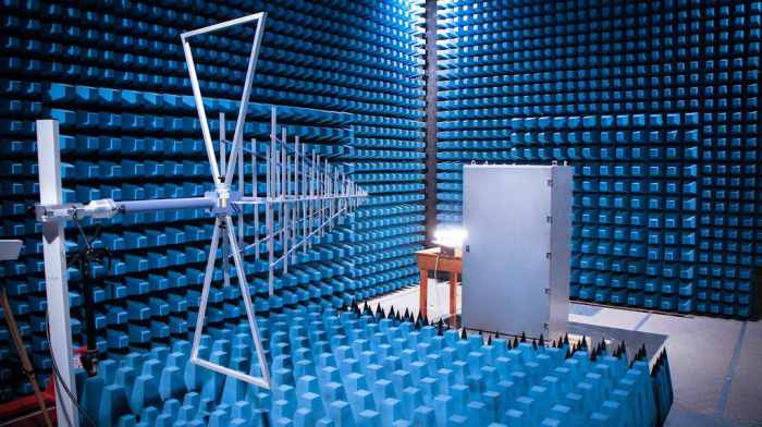
New details for receive antenna positions to be used for test site validation, this refers to A1.1, Figure A.2 and table D.2. This is for site validation which is performed by the test laboratory.
Figure A.2 Examples of the range of receive antenna locations used during NSA Validation of a weather-protected OATS or SAC
Figure A.2 added detailing positions of the antenna placement during NSA validation, this is procedure/validation for the test laboratory.
1.1.5 Methods of exercising displays and video ports updates
Table B.1, an addition has been added to the foot note of the table stating the image may be modified when necessary to exercise the EUT. It then goes onto stating modifications should be restricted to top or bottom half of the screen. Products with displays have so far been fully exercised with live camera images.
Further down in the foot notes there has been a change to the standard for colour bar image (complexity 3 or 4). Within EN 55032:2015+A11, examples are given by specifying BT.471-1, EN 55032:2015+A1 colour bars are now described in Annex J of the standard.
1.2 Annex A
1.2.1 Differences between EN 55032:2015+A11:2020 & EN 55032:2015+A1:2020

Changes to calibration of antennas for radiated emissions
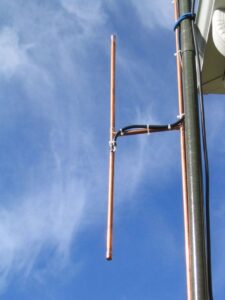
The changes relating to antenna calibration between EN 55032:2015 + A11:2020 and EN 55032:2015 + A1:2020 are mainly clarifications and refinements to ensure more consistent and accurate radiated emission measurements. Antennas are a key part of EMC testing because they detect the electromagnetic fields emitted by multimedia equipment during compliance testing. Accurate calibration of these antennas is essential so that the measured signal can be correctly converted into field strength values used to determine whether a product meets the emission limits defined in the standard.
Amendment A1:2020 introduces improvements to the technical guidance associated with measurement equipment, including antennas used during radiated emission testing. The amendment clarifies requirements for the use of calibrated antennas across the specified frequency ranges and emphasises the importance of applying the correct antenna factor during measurements. The antenna factor represents the relationship between the voltage measured at the receiver and the actual electromagnetic field strength present in the test environment. By clarifying these requirements, the amendment helps ensure that measurements performed by different laboratories remain consistent and comparable.
Another important change in A1:2020 relates to the traceability and documentation of calibration data. Laboratories are expected to ensure that antennas used in testing are calibrated according to recognised calibration procedures and that the calibration results are traceable to national or international standards. This improves confidence in the measurement results and supports the quality management systems used by accredited EMC testing laboratories. The amendment also reinforces the need to consider calibration data and measurement uncertainty when evaluating radiated emission results.
In contrast, A11:2020 does not introduce major new technical requirements for antenna calibration itself. Instead, this amendment mainly focuses on ensuring that the standard remains properly aligned with European regulatory requirements, particularly the Electromagnetic Compatibility Directive 2014/30/EU. The A11 amendment therefore updates references and annexes related to the European harmonisation process rather than making significant changes to the technical calibration procedures described in the standard.
Overall, the difference between the two amendments in relation to antenna calibration is that A1:2020 provides technical clarifications and improvements to measurement practices, while A11:2020 focuses on regulatory alignment within the European framework. As a result, laboratories conducting radiated emission testing must ensure that their antennas are calibrated according to the clarified requirements introduced in A1:2020, while also referencing the harmonised version of the standard that includes A11:2020 for regulatory compliance. These updates help maintain accurate and consistent EMC measurement practices across testing laboratories while ensuring that the standard remains aligned with European legislation.
Methods of excising displays and video ports
Home – EMC Compliance Wiki – Latest Standards – FCC vs CISPR – Fast Transient Bursts – GDPR

PFAS restriction under the REACH framework

REACH 4 February 2026 Candidate Update
Recent EMC Standards Removed from the Harmonised List
Updated Standard

New and Revised Standards for EMC Measurements
ECHA Publishes February 2026 REACH SVHC Update: Two New Substances Added